Post processing basics: Foreground and overlays
Keywords:
Post processing,
effects,
fx
Author(s): Peter Eschler
Date: 2009-03-22
Summary: In this tutorial you will learn the basic concepts for applying post processing effects to an X3D scene using InstantPlayer. It starts by explaining essential nodes like the Foreground and the different Overlay nodes. It then continues to show how to grab the frame buffer and finally presents a basic layout for post-processing effects.
In order to demonstrate the post-processing effects we need a simple test scene. The following code presents a scene containing three standard shapes: a Box, a Sphere and a Torus.
Code: testScene1.x3d, The basic test scene.
<?xml version="1.0" encoding="UTF-8"?>
<!DOCTYPE X3D PUBLIC "ISO//Web3D//DTD X3D 3.0//EN" "http://www.web3d.org/specifications/x3d-3.0.dtd">
<X3D xmlns:xsd='http://www.w3.org/2001/XMLSchema-instance'
     profile='Full' version='3.0'
     xsd:noNamespaceSchemaLocation='http://www.web3d.org/specifications/x3d-3.0.xsd'>

    <Scene DEF='scene'>
        <Viewpoint DEF='vp1' position='0 0 12'/>

        <Transform translation='-3 0 0'>
            <Shape>
                <Appearance><Material diffuseColor="1 0 0" /></Appearance>
                <Box />
            </Shape>
        </Transform>
        <Transform translation='0 0 0'>
            <Shape>
                <Appearance><Material diffuseColor="0 1 0" /></Appearance>
                <Sphere />
            </Shape>
        </Transform>
        <Transform translation='3 0 0'>
            <Shape>
                <Appearance><Material diffuseColor="0 0 1" /></Appearance>
                <Teapot />
            </Shape>
        </Transform>
    </Scene>
</X3D>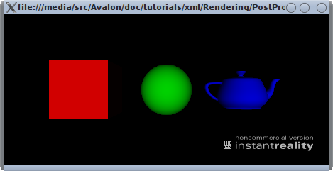
Introducing the Foreground node
For post processing this scene in InstantPlayer we will use a Foreground node.
Warning: The Foreground and most other nodes used in this tutorial are not X3D standard nodes but rather InstantReality extensions. Therefore this example will not work in any X3D runtime/player other than InstantReality.
The documentation of the Foreground node says: "Foreground bindable which holds a list of Overlay nodes. Overlays are simular to layers but not interactive. They are mostly used for visual effects."
As stated in the documentation the Foreground node does not do anything useful until some Overlay nodes are added. To build up our example step by step we first add an empty Foreground to our test scene:
Code: testScene1b.x3d, Added an empty Foreground node.
<Scene DEF='scene'>
    <!-- ... other nodes not shown for brevity -->
    <Transform translation='3 0 0'>
        <Shape>
            <Appearance><Material diffuseColor="0 0 1" /></Appearance>
            <Teapot />
        </Shape>
    </Transform>

    <Foreground />
</Scene>
When you start the testScene1b.x3d example scene, there will be no difference to the testScene1a.x3d. This is simply because the Foreground is empty and thus has no effect on the rendered result. In the next step we will add a PolygonOverlay with a SolidTexture to get some results. So add the following code to the Foreground node:
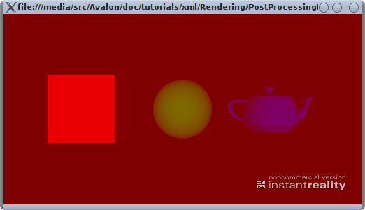
Code: testScene1c.x3d, Added a solid red PolygonOverlay.
<!-- ... other nodes not shown for brevity -->
<Foreground>
    <PolygonOverlay>
        <Appearance><SolidTexture color="1 0 0 0.5" /></Appearance>
    </PolygonOverlay>
</Foreground>
When starting example testScene1c.x3d your scene should render with a red overlay which is half transparent. Because the PolygonOverlay automatically adjusts to the size of the output window you can resize it and your scene will be still covered with red. This can be a problem when using an ImageTexture on the overlay because the texture will be stretched to the dimensions of the window effectively changing the aspect ratio of the texture which will be distorted then. We will learn how to change that behaviour later on in this tutorial, but for now we will use the PolygonOverlay automatically adjusting to the size of the output window.
Adding "useful" textures to the PolygonOverlay
A transparent red overlay does not provide much use, so in the next step we will replace the solid texture of the PolygonOverlay by a custom ImageTexture.
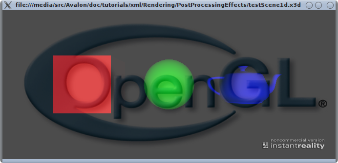
Code: testScene1d.x3d, Added an ImageTexture to the PolygonOverlay.
<!-- ... other nodes not shown for brevity -->
<Foreground>
    <PolygonOverlay>
        <Appearance><ImageTexture url="opengl-logo.png" /></Appearance>
    </PolygonOverlay>
</Foreground>
The texture contains the OpenGL logo and because it is mapped to the polygon of the overlay it fills the whole window. This means that it might be displayed distorted depending on the size of the output window because it's aspect ratio does not match the aspect ratio of the texture.
Warning: Currently it's not possible to use a Material node within the Appearance of the PolygonOverlay. As soon as a Material node is added the ImageTexture will not be shown! In the code above the transparency is encoded into the texture which currently is the only way to make transparency in overlays work.
Fixing the aspect ratio using the "fixedImageSize" field
To solve the problem of overlays being stretched to a wrong aspect ratio you can:
- Make sure that the aspect ratio of the output window is the same as your overlay texture.
- Use the fixedImageSize field of the PolygonOverlay node to specify a fixed texture size.
To deactive the default behaviour of the PolygonOverlay being stretched to fit the whole output window we will use the "fixedImageSize" field of the PolygonOverlay. Despite the name of the field it does not take an image size but rather an aspect ratio. Furthermore the datatype of the field which is SFVec2f is misleading because you can specify float values with a fractional part (e.g. 2.9) but they are treated as integers. If you do specfiy float values with a fractional part they will be floored down to the next integer, i.e. a value of "2.9 1.0" will result in an aspect ratio of "2 1" (and not "3 1" because floor/truncation is used rather than round here).
Warning: The fact that the ratio specified in the fixedImageSize field is treated as integer, any texture used on an overlay needs to have an aspect ratio of full integers (e.g. 4:3, 16:9, 5:7 but not 2.3:5). The OpenGL logo texture in the following example has an aspect ratio of 2:1.
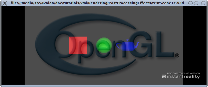
Code: testScene1e.x3d, Added 'fixedImageSize' to the PolygonOverlay.
<Foreground>
    <PolygonOverlay fixedImageSize="2 1">
        <Appearance><ImageTexture url="opengl-logo.gif" /></Appearance>
    </PolygonOverlay>
</Foreground>
This will keep the ImageTexture of the PolygonOverlay at a fixed ratio. The polygon will still be scaled according to the width or height of the output window but it will keep the specified ratio. Try to resize the output window much wider than tall and you will notice that there is some black space to the left and the right of the image.
The TextureGrabOverlay
Besides the PolygonOverlay there exist two additional overlay nodes:
In this tutorial we will focus on the TextureGrabOverlay, which can be used to grab the current content of the frame buffer into a texture. This functionality is the basis for multi-pass post-processing effects.
By simply adding the TextureGrabOverlay after the PolygonOverlay in our test scene, the current frame buffer content is grabbed into the specified texture. Note that we use a SolidTexture here (as it is recommened by the documentation of the texture field, because no initial image is needed).
Warning: The SolidTexture's size field doesn't do anything when used within a TextureGrabOverlay. That's simply because the current frame buffer is grabbed and the target texture is sized according to the size of the frame buffer.
<TextureGrabOverlay>
    <SolidTexture DEF="grabTex1" containerField="texture" />
</TextureGrabOverlay>

<PolygonOverlay >
    <Appearance>
        <SolidTexture USE="grabTex1" />
        <TextureTransform scale="2 2 2" containerField="textureTransform" />
    </Appearance>
</PolygonOverlay>
To be able to see that the grabbed texture is displayed rather than what was in the frame buffer anyway, a TextureTransform node has been added which scales the grabbed texture, effectively showing the grabbed texture 4 times (2x2).
To understand what's displayed in this image and how it correlates to the source code of the scene, let's have a look at this documented code snippet:
<Foreground>
    <!-- At this point the test scene is normally rendered and available in the frame buffer. -->

    <!-- This overlay draws the transparent OpenGL logo over the test scene. -->
    <PolygonOverlay fixedImageSize="2 1">
        <Appearance><ImageTexture url="opengl-logo.png" /></Appearance>
    </PolygonOverlay>

    <!-- This overlay grabs the frame buffer which contains the test scene overlayed
         with the transparent logo into the texture "grabTex1".
         Note that the grab overlay does not clear the frame buffer,
         i.e. the rendered scene with the overlayed logo is still in
         the frame buffer. -->
    <TextureGrabOverlay>
        <SolidTexture DEF="grabTex1" containerField="texture" />
    </TextureGrabOverlay>

    <!-- Now the grabbed texture is overlayed with a scaling (showing it 2x2 times)
         over the current content of the frame buffer (which shines through).
    <PolygonOverlay >
        <Appearance>
            <SolidTexture USE="grabTex1" />
            <TextureTransform scale="2 2 2" containerField="textureTransform" />
        </Appearance>
    </PolygonOverlay>

</Foreground>
Hiding the original frame buffer content
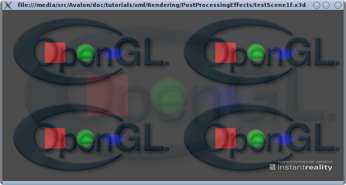
Picking up from the last example it would be nice to be able to remove the original content of the frame buffer which shines through. As it is noted in the code snippet above, the TextureGrabOverlay does not clear the frame buffer, but we can easily achieve this by inserting an additional overlay which does the job for us. The code in testScene1f.x3d shows how to do this:
Code: testScene1f.x3d, Hiding the original frame buffer content.
<TextureGrabOverlay>
    <SolidTexture DEF="grabTex1" containerField="texture" />
</TextureGrabOverlay>

<!-- This overlay effectively clears the framebuffer with a black color. -->
<PolygonOverlay>
    <Appearance><SolidTexture color="0 0 0 1" /></Appearance>
</PolygonOverlay>

<PolygonOverlay >
    <Appearance>
        <SolidTexture USE="grabTex1" />
        <TextureTransform scale="2 2 2" containerField="textureTransform" />
    </Appearance>
</PolygonOverlay>
So that's it for this tutorial. You now have learned the basic concepts for post-processing your scenes and the power of Foreground and Overlay nodes.
Files:
Comments
This tutorial has no comments.
Add a new comment
Due to excessive spamming we have disabled the comment functionality for tutorials. Please use our forum to post any questions.