Humanoid animation
Keywords:
humanoid animation,
h-anim,
virtual humans
Author(s): Yvonne Jung
Date: 2007-11-29
Summary: This tutorial shows how to animate virtual characters with H-Anim.
Overview
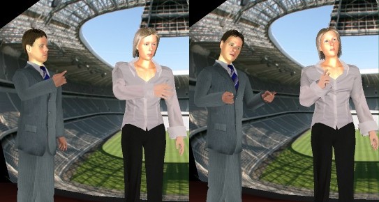
H-Anim figures are articulated 3D representations that depict animated characters. A single H-Anim figure is called a humanoid. While H-Anim figures are intended to represent human-like characters, they are a general concept that is not limited to human beings. Below two links on H-Anim are listed. The first one holds a good introducery overview on the concepts of H-Anim in general, and the second one contains the X3D specification for H-Anim nodes.
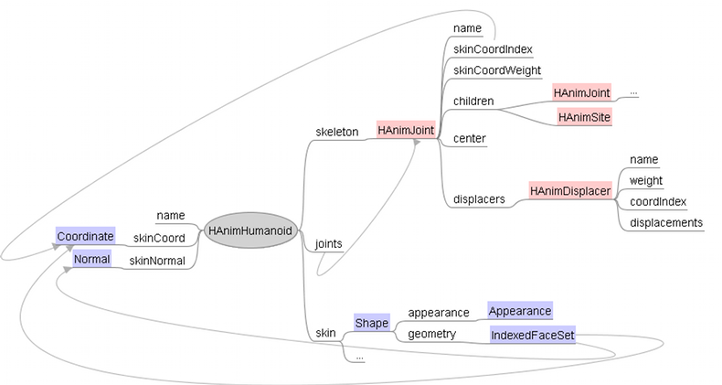
Currently there exist two types of H-Anim figures: Skeletal body geometry describes the body as separate geometric pieces and therefore can lead to artifacts. Skinned body geometry in contrast regards the body as a continuous piece of geometry. Therefore all point and normal vector data sets are defined in one place, in the 'skinCoord' and 'skinNormal' fields of the HAnimHumanoid, for allowing smooth mesh animations. In this tutorial only the latter, more natural looking type is described.
The 'skin' field of the HAnimHumanoid node contains the real mesh information, i.e. the Shape nodes, which define appearance and geometry of certain body parts like face or legs. As can be seen in the next code fragment, the Geometry's 'coord' and 'normal' fields only hold references to the Coordinates and Normals already defined in the 'skinCoord' and 'skinNormal' fields of the HAnimHumanoid. This way a seemless animation is achieved both for the vertices and the normals without the need to recalculate the latter.
Animation
The HAnimJoint node is used to describe the articulations of the humanoid figure. Each articulation is represented by an HAnimJoint node. These joints are organized into a hierarchy of transformations that describes the parent-child relationship of joints of the skeleton and provides a container for information that is specific to each joint. This transformation hierarchy is listed in the 'skeleton' field of the HAnimHumanoid node. An additional field 'joints' holds references to all used HAnimJoint nodes.
An HAnimJoint has two fields that allow it to manipulate individual vertices defined within the skinCoord field of the HAnimHumanoid node. Incoming rotation or translation events of the joint affect the vertices indicated by the 'skinCoordIndex' field by a factor that is described by the corresponding values within the 'skinCoordWeight' field. The MFFloat field 'skinCoordWeight' contains a list of values that describe the amount of weighting to be used to affect the appropriate vertices, as indicated by the skinCoordIndex field, of the humanoid's 'skinCoord' and 'skinNormal' fields.
Code: Structure and usage of skinned H-Anim nodes
DEF HUMANOID HAnimHumanoid {
    name "Charles"
    skeleton [
        DEF hanim_HumanoidRoot HAnimJoint {
            name "HumanoidRoot"
            center 0 .9723 -.0728
            skinCoordIndex [
                0 1 2 3 4 5 6 7 8 9 10 11
            ]
            skinCoordWeight [
                1 1 1 1 1 1 1 1 1 1 1 1
            ]
            children [
                DEF hanim_l_hip HAnimJoint {
                    name "l_hip"
                    center .0956 .9364 0
                    skinCoordIndex [
                        #...
                    ]
                    skinCoordWeight [
                        #...
                    ]
                    children [
                        #...
                    ]
                }
                DEF hanim_r_hip HAnimJoint {
                    name "r_hip"
                    #...
                }
                #...
            ]
        }
    ]
    joints [
        USE hanim_HumanoidRoot
        USE hanim_r_hip
        USE hanim_l_hip
        #...
    ]
    skinCoord DEF hanim_skin_coord Coordinate {
        point [
            #...
        ]
    }
    skinNormal DEF hanim_skin_normal Normal {
        vector [
            #...
        ]
    }
    skin [
        DEF faceShape Shape {
          appearance Appearance {
            texture ImageTexture {
              url "headTexture.jpg"
            }
          }
          geometry IndexedFaceSet {
            coord USE hanim_skin_coord
            normal USE hanim_skin_normal
            normalUpdateMode "none"
            coordIndex [
                #...
            ]
            normalIndex [
                #...
            ]
          }
        }
        #...
    ]
}

DEF TIMER TimeSensor {
    loop TRUE
    cycleInterval 5
}

DEF HUMANOIDROOT_POS_ANIMATOR PositionInterpolator {
    key []
    keyValue []
}
DEF HUMANOIDROOT_ANIMATOR OrientationInterpolator {
    key []
    keyValue []
}
DEF L_HIP_ANIMATOR OrientationInterpolator {
    key []
    keyValue []
}
DEF R_HIP_ANIMATOR OrientationInterpolator {
    key []
    keyValue []
}
#...

ROUTE TIMER.fraction_changed TO HUMANOIDROOT_POSITION_ANIMATOR.set_fraction
ROUTE TIMER.fraction_changed TO HUMANOIDROOT_ANIMATOR.set_fraction
ROUTE TIMER.fraction_changed TO L_HIP_ANIMATOR.set_fraction
ROUTE TIMER.fraction_changed TO R_HIP_ANIMATOR.set_fraction
#...
ROUTE HUMANOIDROOT_POS_ANIMATOR.value_changed TO hanim_HumanoidRoot.set_translation
ROUTE HUMANOIDROOT_ANIMATOR.value_changed TO hanim_HumanoidRoot.set_rotation
ROUTE L_HIP_ANIMATOR.value_changed TO hanim_l_hip.set_rotation
ROUTE R_HIP_ANIMATOR.value_changed TO hanim_r_hip.set_rotation
#...
The HAnimSegment node is a specialized grouping node that can only be defined as a child of an HAnimJoint node. It represents body parts of the humanoid figure and is organized in the skeletal hierarchy of the humanoid. The HAnimSite node can be used to define an attachment point for accessories such as jewelry and clothing on the one hand and an end effecter location for an inverse kinematics system on the other hand. Both nodes usually are not needed for skinned body animation.
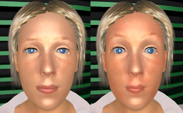
The HAnimDisplacer nodes are usually used to control the shape of the face. Each HAnimDisplacer node specifies a location, called a morph target, that can be used to modify the displacement properties of the corresponding vertices defined by the 'coordIndex' field. The scalar magnitude of the displacement is given by the 'weight' field and can be dynamically driven by an interpolator or a script. The next code fragment shows an example. The mesh therefore can be morphed smoothly using the base mesh and a linear combination of all sets of displacement vectors, given by the MFVec3f 'displacements' field of the HAnimDisplacer nodes.
Code: Using a displacer for facial animation
DEF Head HAnimJoint {
    name "Head"
    center 0 1.58 0.03
    skinCoordIndex [
        0  1  2  3  4  5  6  7  8  9  10 #...
    ]
    skinCoordWeight [
        1 1 1 1 1 1 1 1 1 1 #...
    ]
    displacers [
        DEF Phon_AShape HAnimDisplacer {
            name "Phon_AShape"
            weight 0.0
            coordIndex [
                0 1 2 3 4 5 6 7 8 9 10 #...
            ]
            displacements [
                0.000000 0.000000 0.000500,
                -0.002130 -0.002270 0.006110,
                #...
            ]
        }
        DEF Idle_Blink_bothShape HAnimDisplacer {
            #...
        }
    ]
}

DEF Timer TimeSensor {
    loop TRUE
    cycleInterval 5
}

DEF Interpol ScalarInterpolator {
    key [ 0.0, 0.25, 0.5, 0.75, 1.0 ]
    keyValue [ 0.0, 0.25, 0.5, 0.25, 0.0 ]
}

ROUTE Timer.fraction_changed TO Interpol.set_fraction
ROUTE Interpol.value_changed TO Idle_Blink_bothShape.weight
ROUTE Interpol.value_changed TO Phon_AShape.weight
Morphing
Quite similar to the already described Displacer node is the CoordinateMorpher node. Assume you want to animate a face, and you have given, say n, target states of your modelled face, a neutral one, and n-1 other ones, e.g. a smiling one, one with open eyes, one with closed eyes, one with raised eyebrows, one saying 'a', and so on.
The Morpher node regards each of these states as a base vector of an n dimensional space spanning all possible combinations of point sets. In order to get valid linear combinations be careful that the coefficients (weights) of your data points (i.e. sets of expressions, which are also called morph targets) sum up to 1 (which is called a convex combination).
In the code fragment shown below we want to interpolate between a neutral state (the first one or 'keyValue' No 0 respectively) and state No 10. Therefore additionally a VectorInterpolator is needed. For each key time a vector of nkeyValues is needed, defining the maximum weight for all morph targets (please note, that all lines sum up to 1). Another important thing to keep in mind, is that the sequence of points must not change, because they all belong to the same index field.
Code: A vector interpolator with 15 states, neutral is at position 0.
Shape {
    appearance Appearance {}
    geometry IndexedFaceSet {
        coord DEF coords Coordinate {
            point [
                0.086, 0.050, 0.431, 0.089, 0.044, 0.434,
                #...
            ]
        }
        coordIndex [
            0, 1, 2, -1, 3, 4, 5, -1,
            #...
        ]
    }
}

DEF morph CoordinateMorpher {
    keyValue [
        # 15 sets of coordinates; one set for each state:
        0.086, 0.050, 0.431, 0.089, 0.044, 0.434,
        #...
    ]
}

DEF vipol VectorInterpolator {
    key [ 0.0, 0.1, 0.75, 1.0 ]
    keyValue [
        1.0  0    0    0    0    0    0    0    0    0    0    0    0    0    0,
        0.4  0    0    0    0    0    0    0    0    0    0.6  0    0    0    0,
        0.6  0    0    0    0    0    0    0    0    0    0.4  0    0    0    0,
        1.0  0    0    0    0    0    0    0    0    0    0    0    0    0    0,
    ]
}

DEF ts TimeSensor {
    loop TRUE
    cycleInterval 5
}

ROUTE ts.fraction_changed TO vipol.set_fraction
ROUTE vipol.value_changed TO morph.set_weights
ROUTE morph.value_changed TO coords.set_point
The first of the attached files shows a simple but skinned walking character whereas the second file shows the morpher in action for doing simple facial animation.
Files:
Comments
This tutorial has no comments.
Add a new comment
Due to excessive spamming we have disabled the comment functionality for tutorials. Please use our forum to post any questions.